Projektid – Eesti
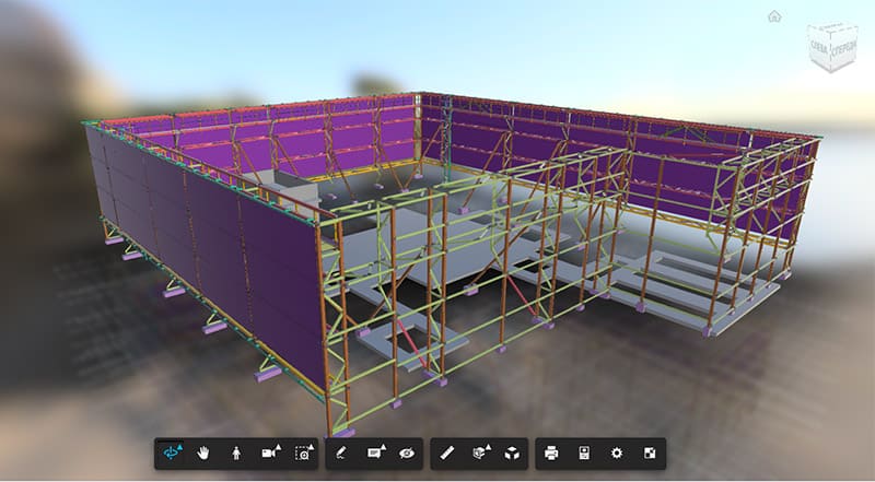
Betoonist kokkupandav disain (armatuur, 3D-modelleerimine, WSD)
TARKVARATOOTED: Tekla Structures, Tekla Model Sharing, Dlubal RFEM
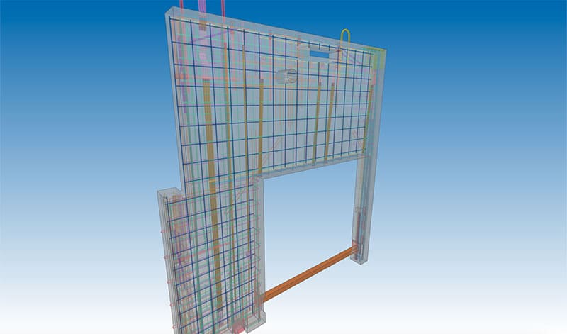
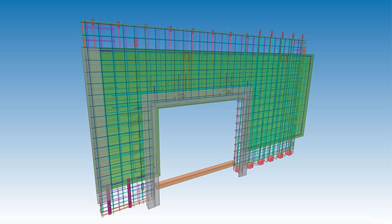
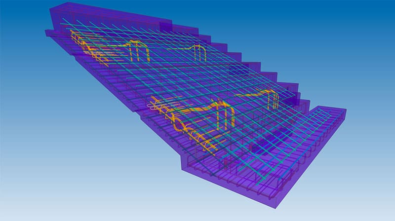
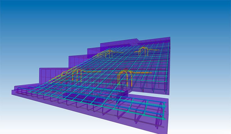
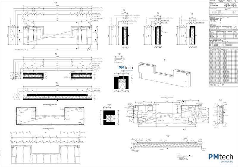
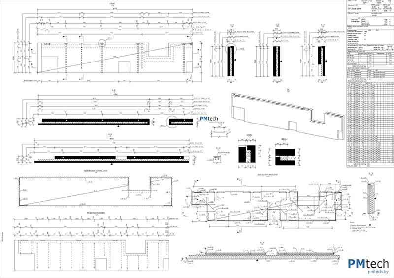
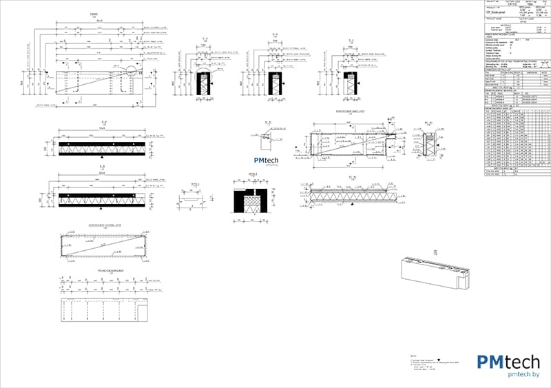
Eelpaneelkonstruktsioonid koguvad populaarsust tänu paremale kvaliteedikontrollile, lühematele ehitusaegadele ja keskkonnasõbralikumale lähenemisele võrreldes monoliitsete konstruktsioonidega.
Ehitise projekteerimisel monteeritavatest konstruktsioonidest pöörab PMtech Engineering erilist tähelepanu konstruktsioonilahendustele, hoone tugevusele, stabiilsusele ja vastupidavusele ning kasutatavatele materjalidele.
Selliste projektide kallal töötades pööratakse erilist tähelepanu kohalikele tootjatele, konstruktsioonide ja monteeritavate elementide tootjate nõuetele ja nende nomenklatuurile, mis võimaldab tulevikus logistikat asjatundlikult korraldada ja elemente ehitusplatsile minimaalse kuluga tarnida. Seejärel edastati kogu vajalik dokumentatsioon (keeruliste individuaalsete elementide tööjoonised) tehasele, kus nende andmete põhjal valmistati kõik vajalikud paneelid. Lõppfaasiks oli valminud elementide saatmine ehitusplatsile paigaldamiseks
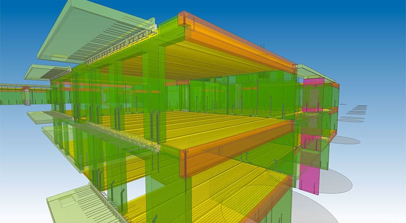
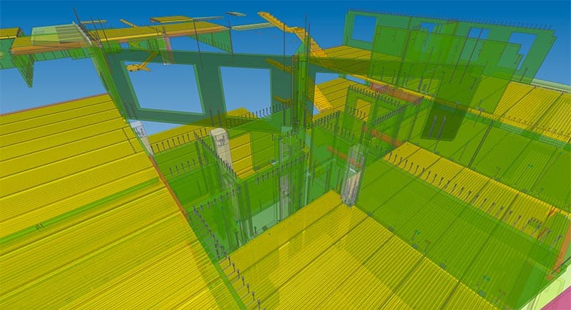
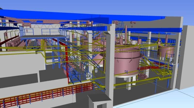
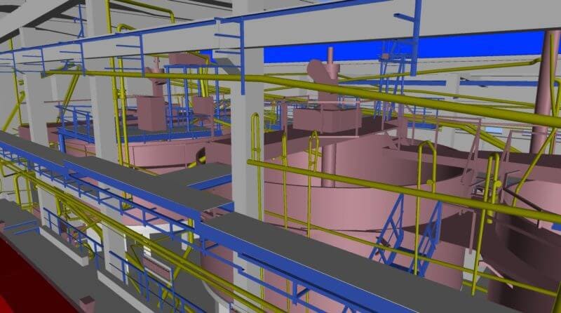
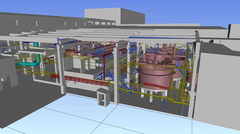
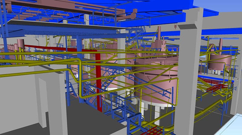
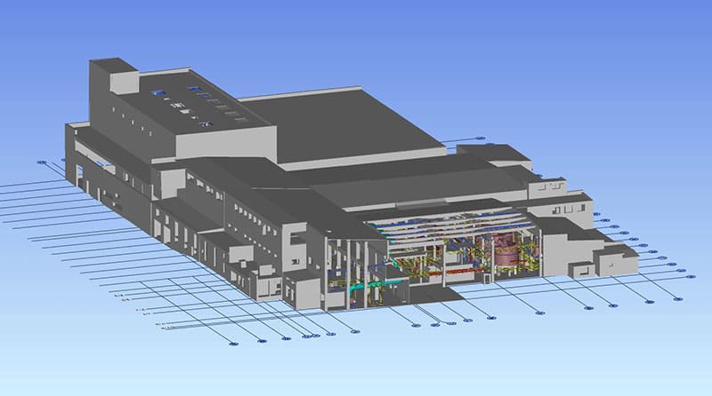
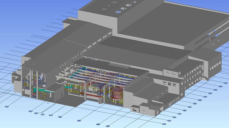
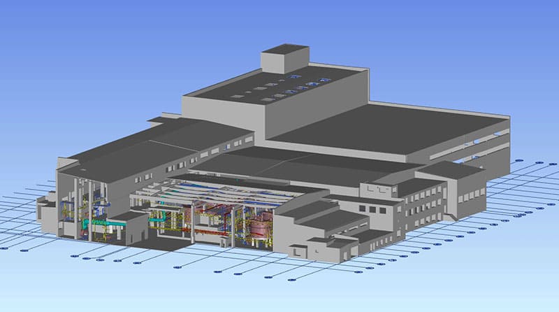
Keemiatööstuse, kaevanduste ja metallide kompleksi 3D BIM-mudel
TARKVARATOOTED: AUTODESK REVIT, AUTODESK NAVISWORKS
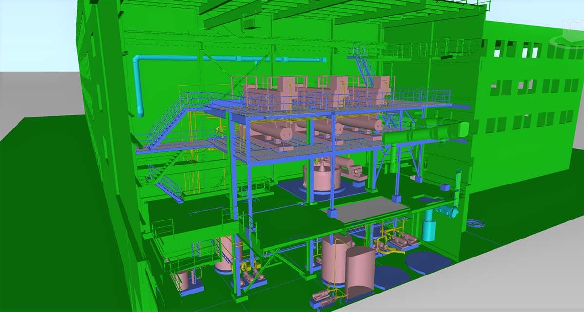
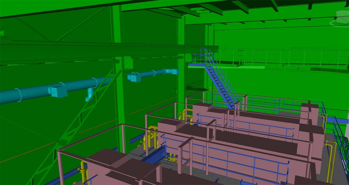
Kuna olemasolev 2D dokumentatsioon oli, viidi läbi projekt „3D BIM-mudel keemiatööstuse, kaevanduste ja metallide kompleksile“ toetava konstruktsiooni sektsioonide atribuutide täitmiseks ja 3D mudeli loomiseks.
3D mudeli loomisel viidi läbi kokkupõrgete, spetsifikatsioonide ja deklaratsioonide analüüs, et leida optimaalsed lahendused materjalide valikuks, nende omadusteks ning omadusteks raudbetooni ja metallkonstruktsioonide puhul. Projekti lõpetamisel kiideti kõik rakendatud lahendused edukalt heaks spetsialistide ja organisatsioonide poolt, kes osalesid objekti arenduses ja projekteerimises.
BIM-mudeli „As designed“ väljatöötamine on efektiivne lahendus paberdokumentide või aegunud andmetüüpidest üleminekuks, kuna 3D-mudelile üleminekul tuvastatakse ja parandatakse olulisi vigu ja kokkupõrkeid. Tehniliselt õiged BIM-andmed võimaldavad tõhusalt ja asjatundlikult jaotada eelarvet hoone või konstruktsiooni ehitamiseks, ümberkujundamiseks ja kasutamiseks
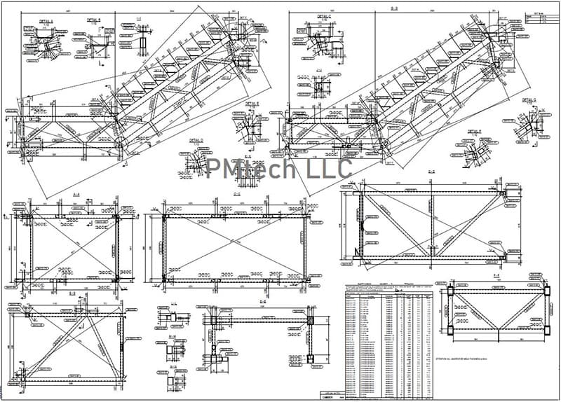
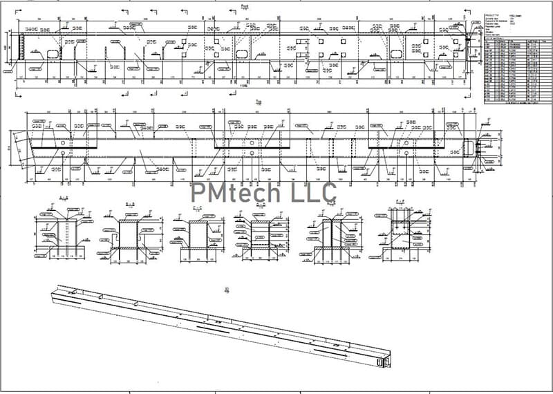
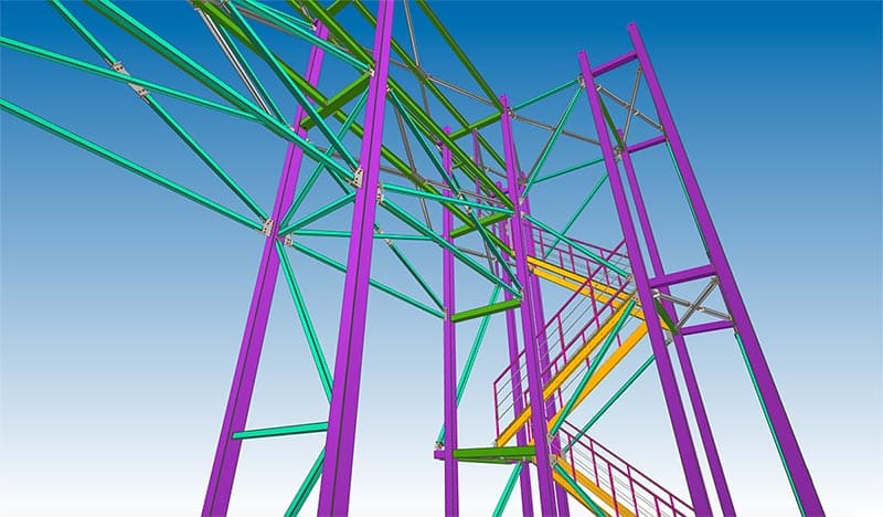
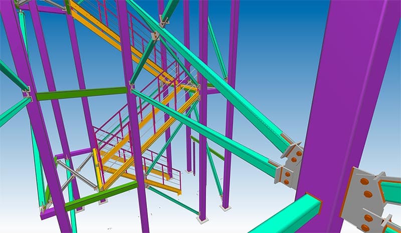
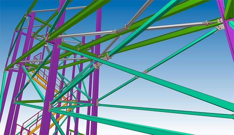
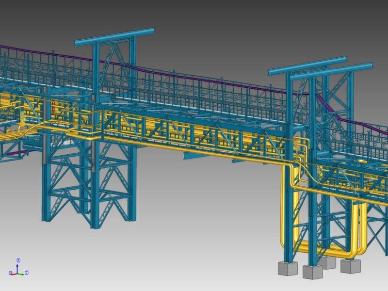
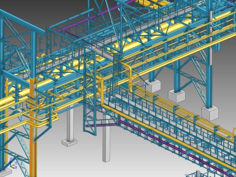
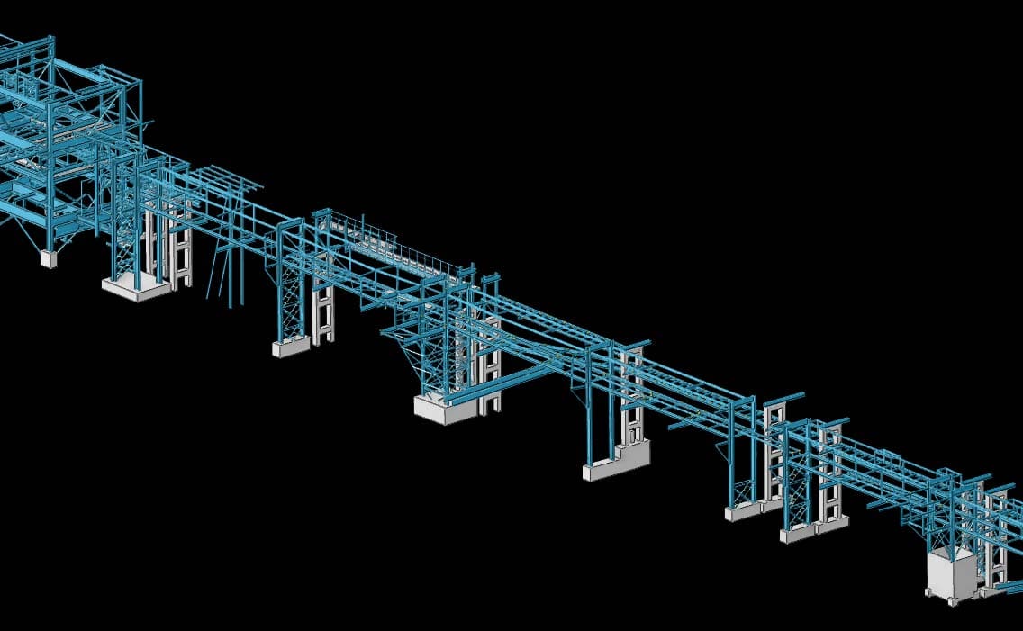
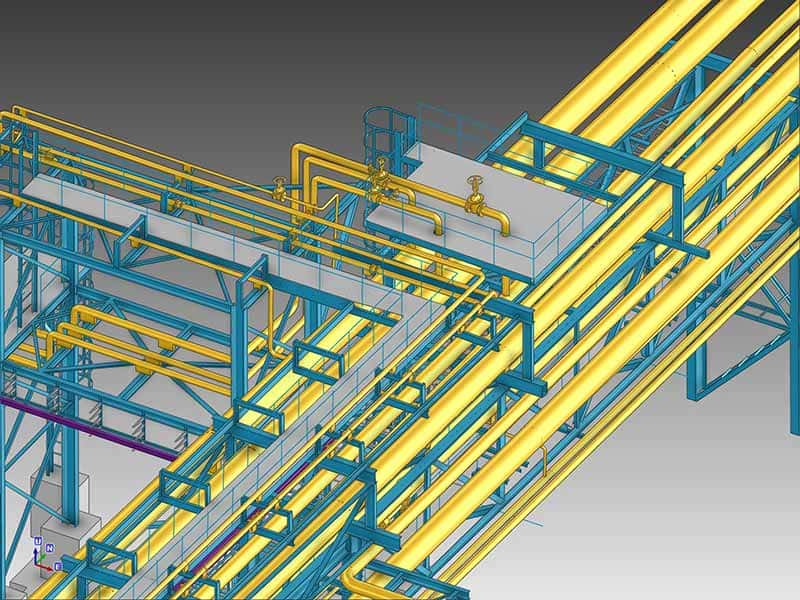
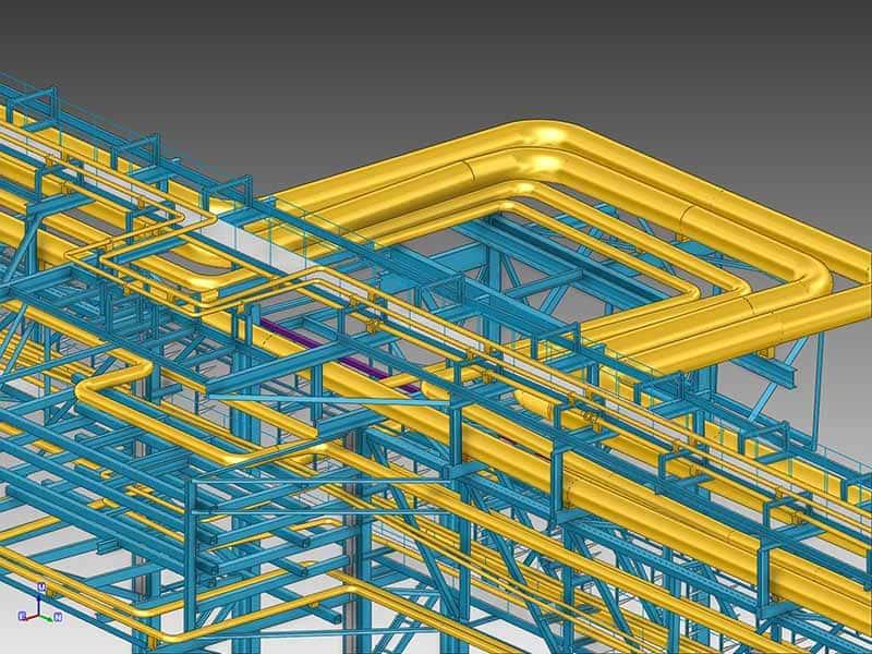
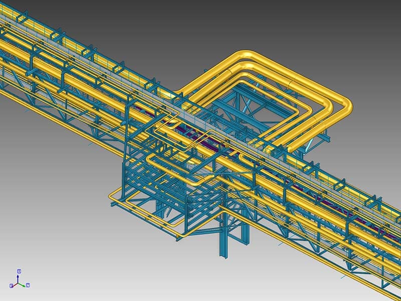
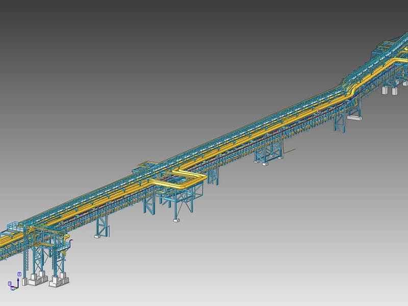
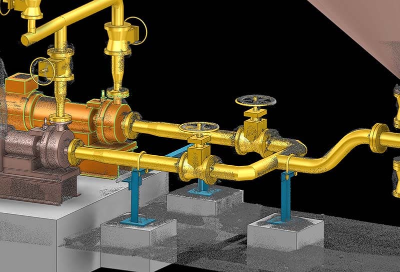
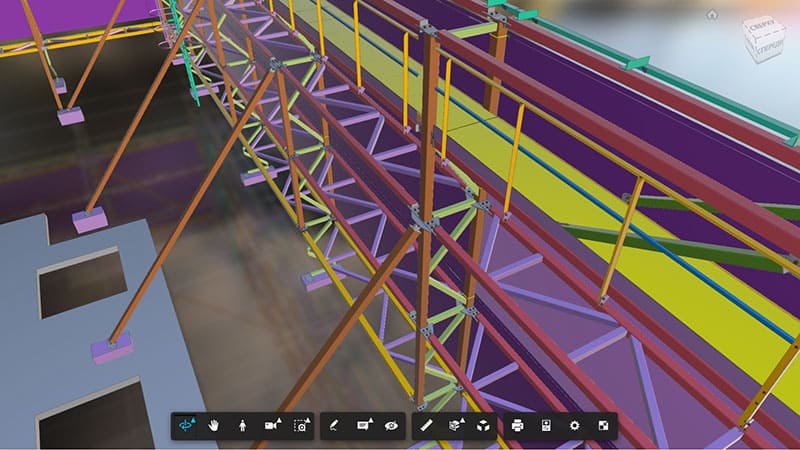
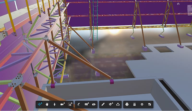
Teraskonstruktsioonide projekteerimine (3D modelleerimine, detailimine, WSD)
TARKVARATOOTED: AUTODESK REVIT, TEKLA STRUCTURES, AUTODESK NAVISWORKS
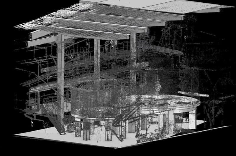
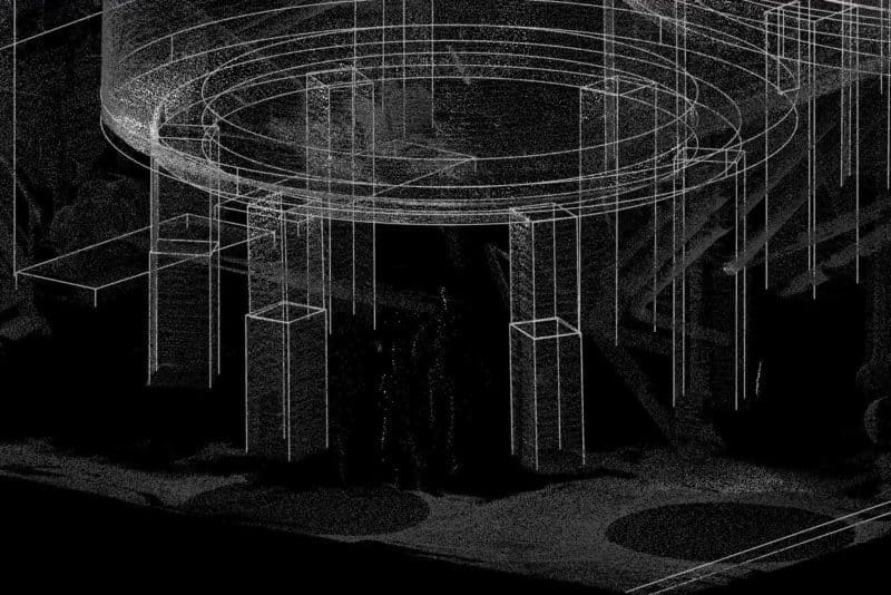
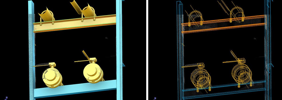
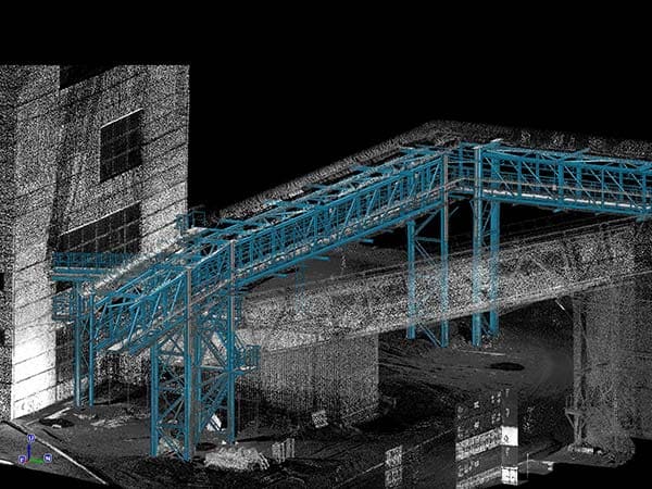
Punktipilve põhjal loodud 3D-mudel
TARKVARATOOTED: AUTODESK REVIT, AUTODESK NAVISWORKS
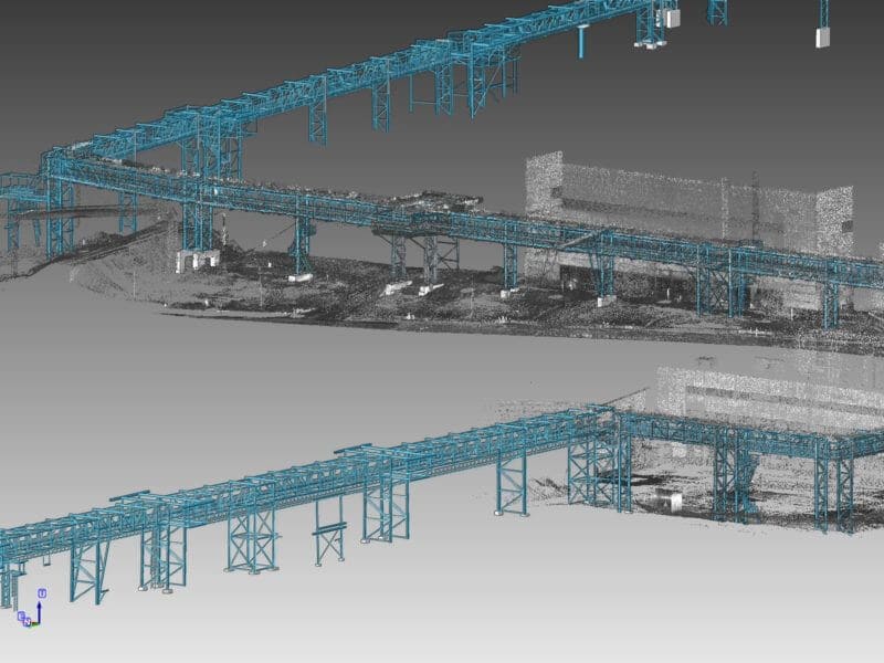
Selle projekti “As built” mudeli loomine põhines 3D-laserskaneerimise tehnoloogia abil saadud punktipilve teabel. Pärast töödeldud punktipilve saamist tehti import CAD-süsteemi, kus viidi läbi edasine 3D modelleerimine.
Lõpetatud mudel kuvab objekti tegelikku seisundit uurimise ajal ja peegeldab läbi viidud inseneri- ja geodeetiliste uuringute tulemusi. Selle meetodi eeliseks on see, et kliendil on lühikese aja jooksul võimalik saada detailne täitevv mudel nii lihtsast kui ka keerulisest insenerrajatisest, mis on vajalik edasiseks kasutamiseks ja rekonstrueerimiseks.
Ehitusprotsessi käigus punktipilve kogumine ja objekti mudeli kasutamine igas etapis võimaldab tuvastada ja parandada tekkinud kokkupõrkeid ja vigu, mis tagab tööde tegemise ehitus- ja paigaldusetapis ilma paranduste ja viivitusteta. Punktipilve põhjal loodud 3D-mudel tagab tööohutuse ja vähendab projekti kulusid oluliselt.
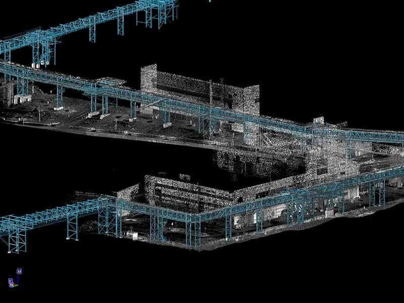
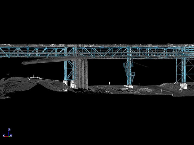
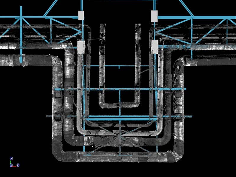
Punktipilve põhjal loodud tehnoloogilise kompleksi 3D-mudel
TARKVARATOOTED: AUTODESK REVIT, AUTODESK NAVISWORKS
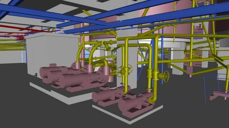

Selle projekti peamine ülesanne oli luua parameetriline 3D-mudel edasise lisaseadmete projekteerimise, töökoja sisemiste süsteemide rekonstrueerimise ja seadmete moderniseerimise jaoks. Eripära seisneb selles, et punktipilve saamine skaneerimise teel viidi läbi tootmisprotsessi katkestamata.
Skaneerimise järel saadi detailne teave aktiivse objekti geomeetria kohta, sealhulgas: kõigi korruste ja seinte paksused, avade mõõdud, kõrguse märgid, kaarte kalle ja muud andmed. Edasi arendati täitevv BIM-mudel – mudel, kus iga element sisaldas projekteerimiseks vajalikke tehnilisi ja tehnoloogilisi omadusi.
Selle projekti näitel saab taas näha, kuidas kaasaegsed mõõtmistehnoloogiad aitavad kiirendada rekonstrueerimisprotsessi ja tänu BIM-mudelile, mis on ehitatud punktipilve põhjal, saab rekonstrueerimist ja moderniseerimist teha millimeetri täpsusega.
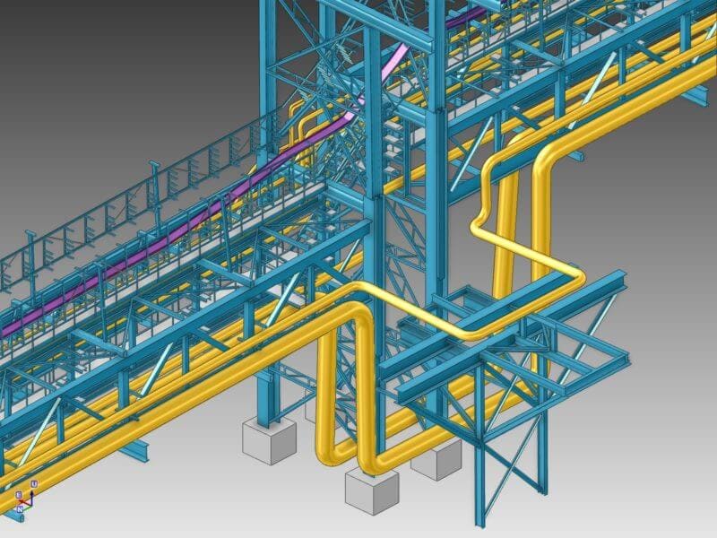
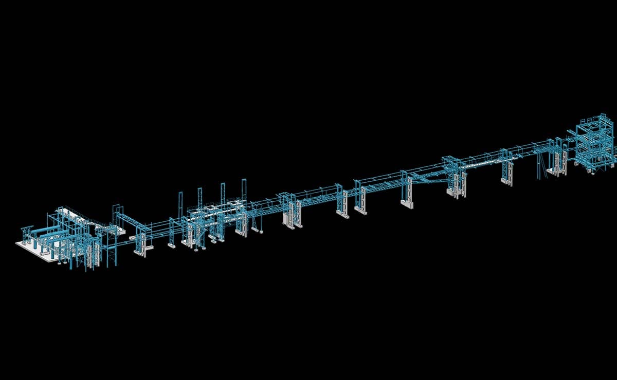
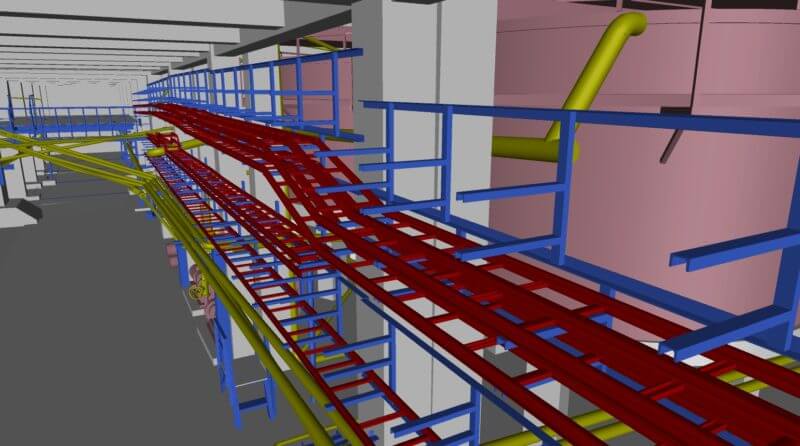
Tööstuskompleksi 3D-mudeli loomine
TARKVARATOOTED: AUTODESK REVIT, AUTODESK RECAP, AUTODESK NAVISWORKS
Tööstuslike objektide 3D-mudelite loomisel kasutatakse erinevaid meetodeid ja tööriistu, mis võimaldavad koguda teavet objektide kohta ja koostada selle põhjal dokumentatsiooni. Mudel ise on teabehoidla objektist, mis on vajalik edasise rekonstrueerimise, moderniseerimise jaoks ning pakub võimalust planeerida ajakulu ja rahalisi kulutusi, tuvastada probleeme ristumiskohtades (kokkupõrked) ja hinnata tulemuslikkust.
See meetod võimaldas teha uuringu lühikese aja jooksul, töödelda saadud punktipilve ja luua detailne 3D-mudel edasiseks kasutamiseks kliendi poolt. Hoolimata piirangutest, mis tekkisid keeruliste nähtavusolude ja objekti omaduste tõttu, kajastas digitaalne kaksik töö lõppedes reaalse objekti täpset andmestikku elektroonilises formaadis.
Objekti BIM-mudeli loomise põhjused olid järgmised:
-
tulevase rekonstrueerimise ja metallurgilise kompleksi tööstusliku töökoja olemasolevate konstruktsioonide demonteerimise läbiviimine;
-
uute konstruktsioonide ehitamine ja konfliktivaba sidumine uuritud töökoja osadega valmis BIM-mudeli ja olemasoleva teabe põhjal.
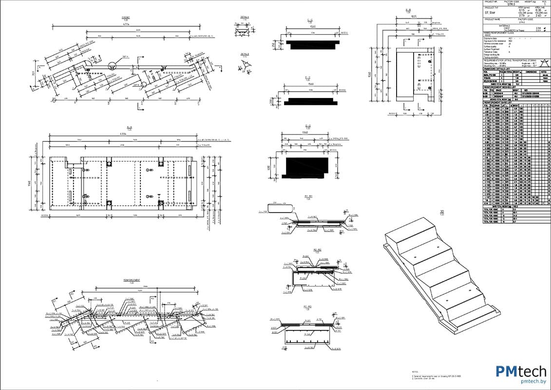
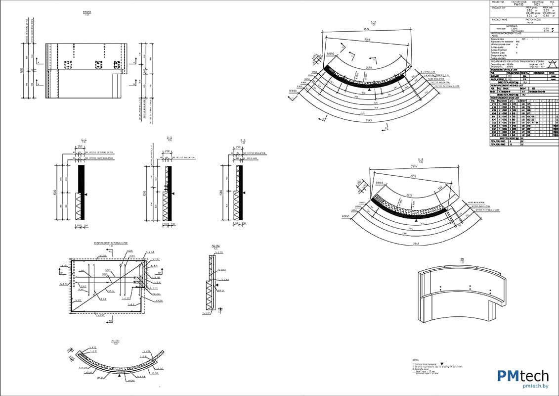
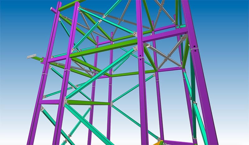
Konstruktsioonide ja ehitusaiade projekteerimine
TARKVARATOOTED: TEKLA STRUCTURES, IDEAStatica
Metallkonstruktsioonide projekteerimine on aeganõudev ja vastutustundlik protsess, mis nõuab kliendi, projekteerimisosakonna ja tootmise osalust. Projekteerimisdokumentatsiooni loomine, mis hõlmab metallkonstruktsioonide detailsete jooniste väljatöötamist, eeldab kõigi normide, standardite ja õiguslike arvutuste järgimist spetsialistide poolt.
Selles projektis teostas meie ettevõte tööd 3D-mudeli loomisel Tekla Structures’is ja tehasejooniste väljastamisel metallkaare jaoks sissepääsugruppi üle. Need joonised eristuvad absoluutse detailikuse poolest ja sisaldavad jälgitavaid elemente: seonduvad üksikasjad, aukude suurused, keevitusomadused. Meie töötajate professionaalne lähenemine võimaldas luua selged ja täpsed monteerimisjoonised, samuti informatiivsed kokkupanemise joonised, mis lihtsustavad ja kiirendavad teraskonstruktsiooni elementide monteerimist keskse sissepääsuvärava jaoks.
Arvestades lõpetatud metallkonstruktsiooni eeliseid, mis toodi välja töö lõpuleviimise järel: ökoloogiline kasu – tooted valmistati ilma jäätmeteta; kaare kõrge tugevus; mugavus ja ajasääst valmis ja arusaadavate jooniste järgi monteerimisel