Industrial facility
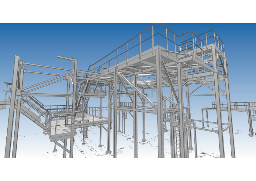
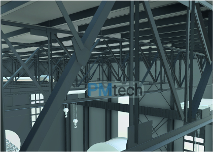
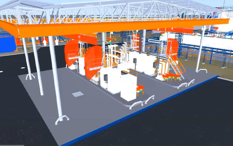
Showcasing our expertise in steel structure design for an EU industrial plant
SOFTWARE PRODUCTS: TEKLA STRUCTURES, DLUBAL RFEM, IDEA STATICA
PROJECT INFORMATION
Industrial facility. Energy Plant
PROJECT DESCRIPTION
We are proud to share another successful steel structure design for industrial project completed in Lithuania
Every industrial project comes with unique challenges, and this one was no exception. Here are some key challenges we faced and how our engineering team successfully addressed them:
1. Complex Structural Requirements
The industrial plant required a highly durable and precisely designed steel framework to support heavy equipment and withstand high temperatures. Our engineers conducted in-depth structural analysis and optimized material usage to ensure stability and longevity
2. Precision in 3D Steel Detailing
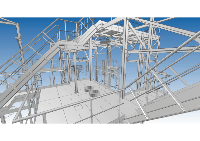
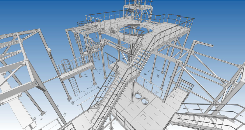
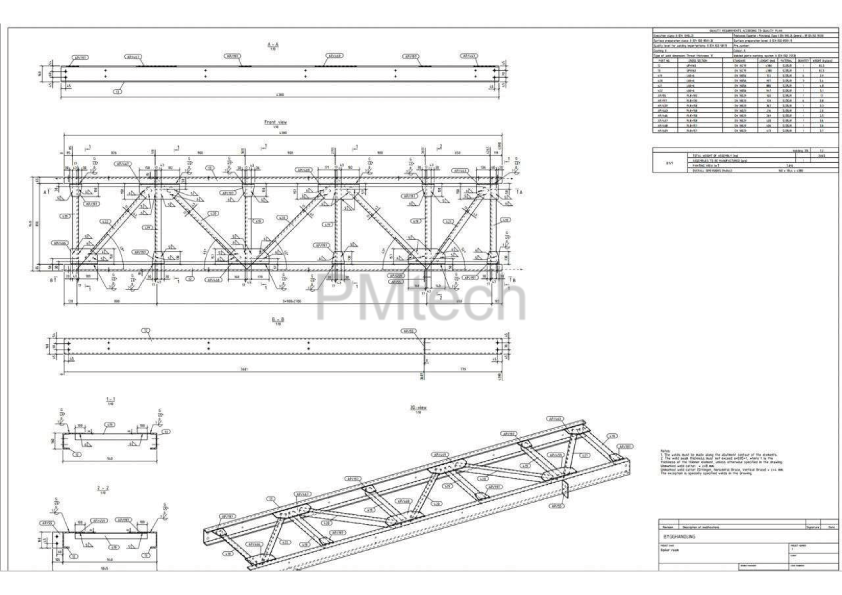
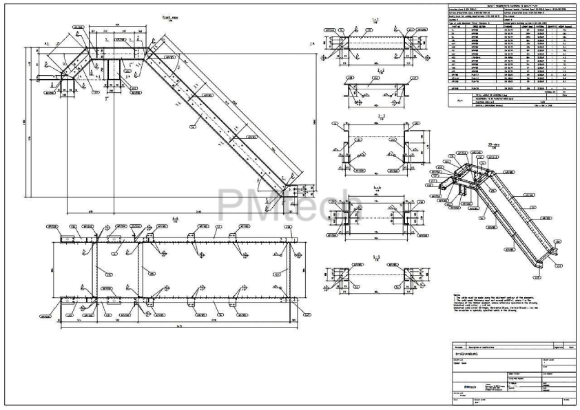
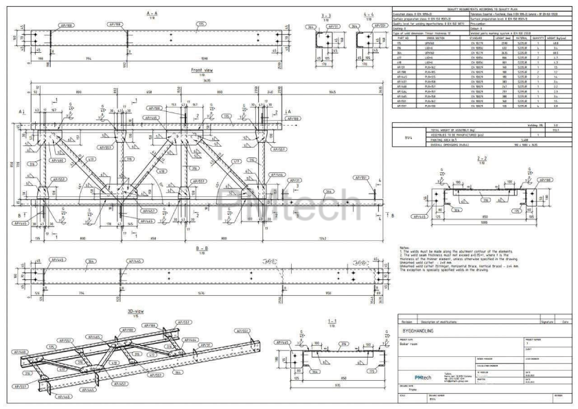
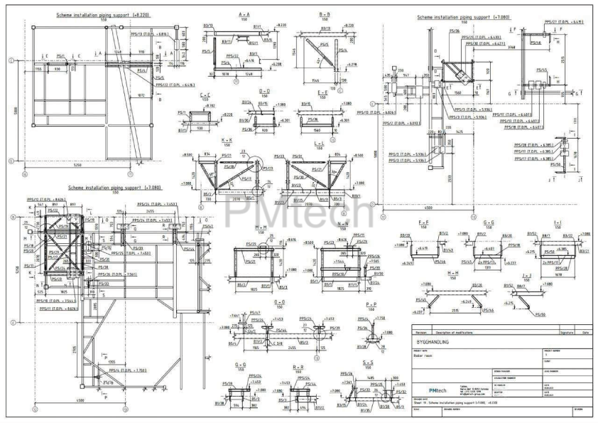
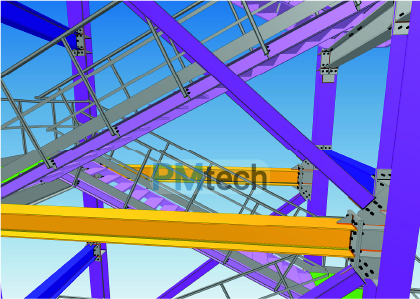
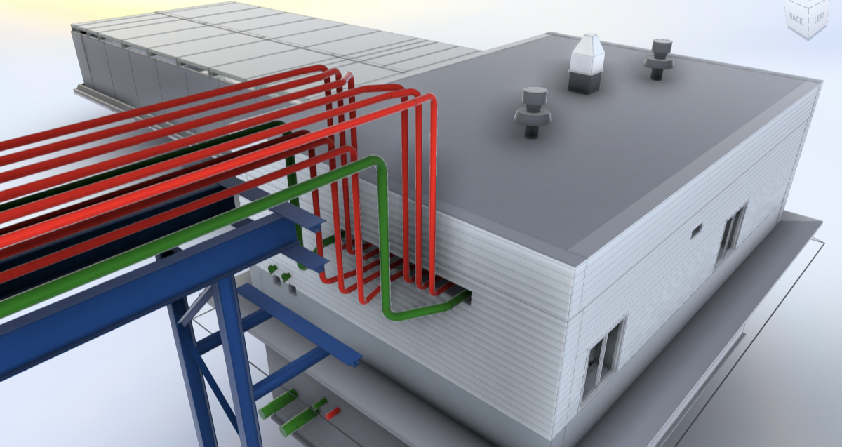
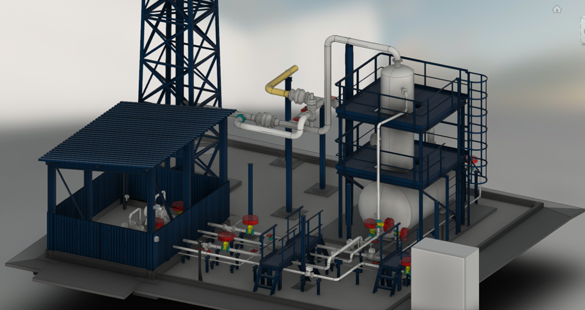
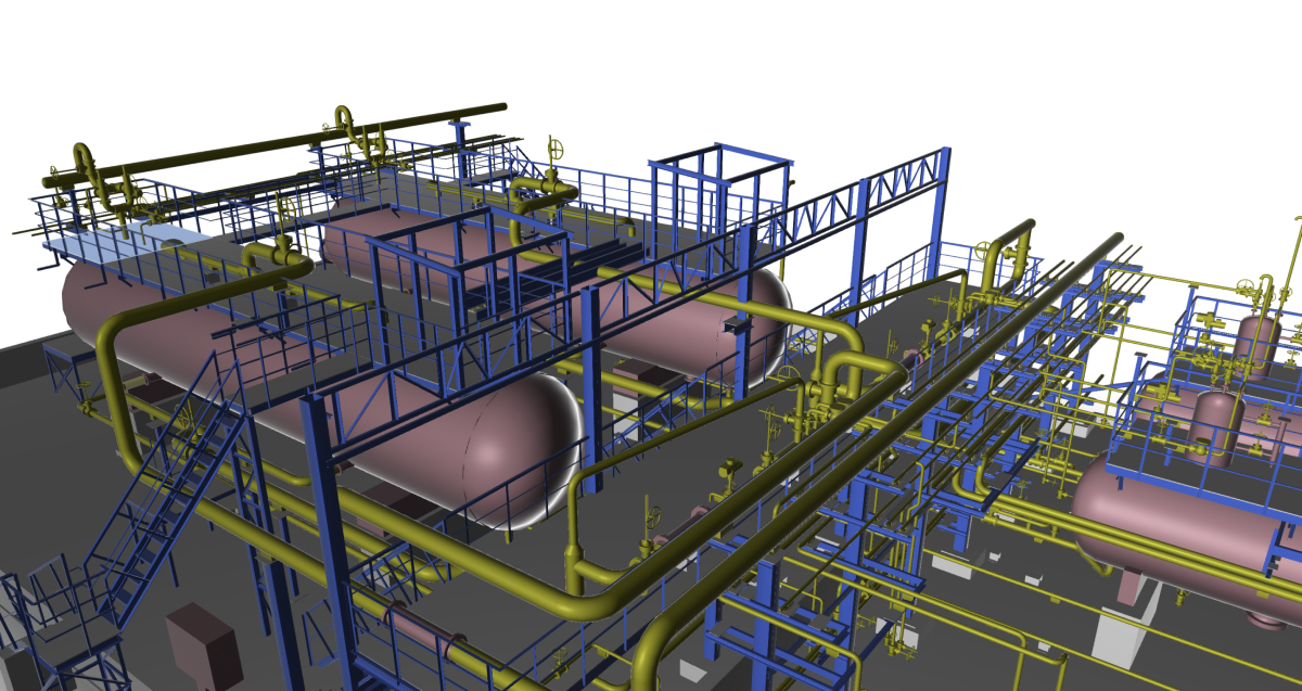
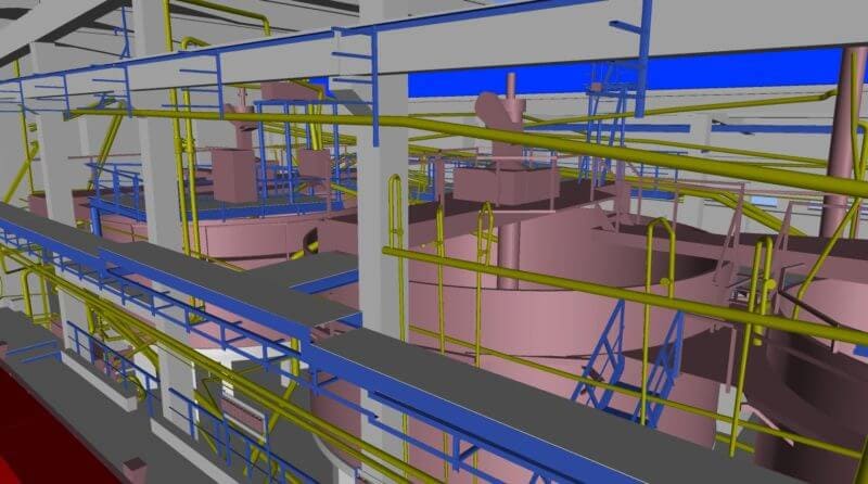
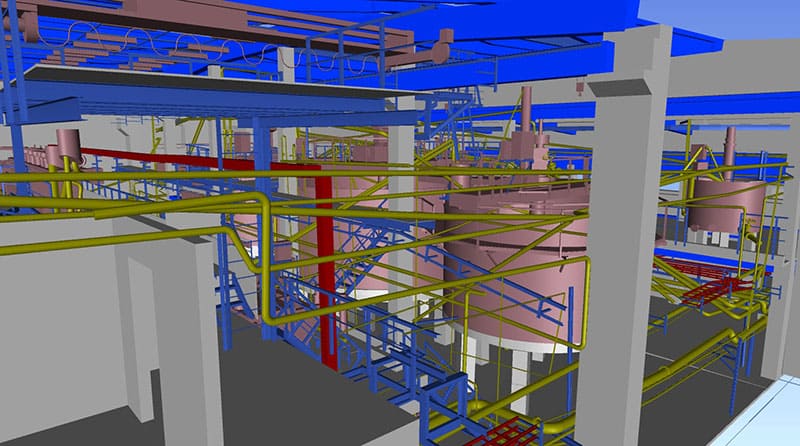
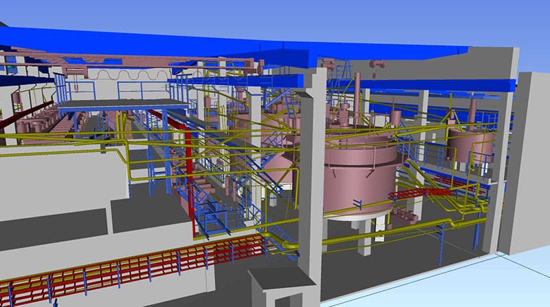
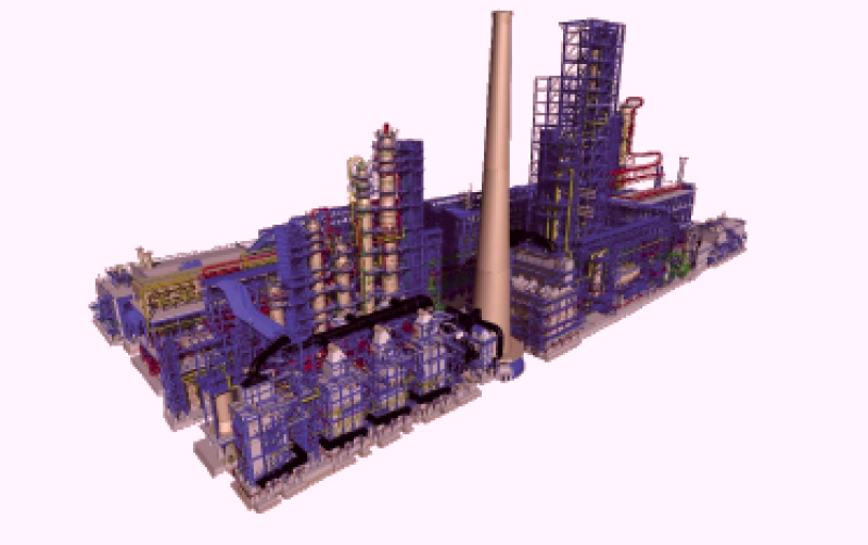
We used Tekla Structures to create highly detailed 3D models for all structures – technological equipment framing, steel stairs, and maintenance platforms, allowing for error-free fabrication and installation.
3. BIM coordination with Other Disciplines
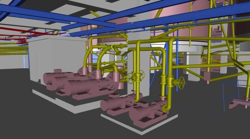
The integration of the steel framework with the plant’s equipment and ventilation systems required precise coordination. We worked closely with mechanical and electrical engineers, ensuring seamless integration through BIM coordination.
For this industrial project, our scope of work included:
– Development of construction drawings
– 3D steel detailing using Tekla Structures
– Workshop drawings for fabrication
By leveraging advanced 3D modeling and detailing techniques, we ensured high precision, optimized material usage, and seamless coordination between design and fabrication. Our team’s expertise and commitment to quality allowed us to deliver accurate, efficient, and cost-effective solutions for the client.
Key Achievements:
✔ High-accuracy steel detailing, reducing on-site modifications
✔ Optimized material usage for cost efficiency
✔ Seamless integration with other disciplines through BIM coordination
Shop Drawings vs General Arrangement Drawings
SOFTWARE PRODUCTS: AUTODESK REVIT, AUTODESK NAVISWORKS
PROJECT INFORMATION
Understanding the Differences.
As an engineer working in the field of steel detailing, it is essential to understand the disparities between shop drawings and general arrangement (GA) drawings. While both play significant roles in the construction process, they serve distinct purposes and provide unique information
PROJECT DESCRIPTION
General Arrangement (GA) Drawings
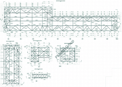
GA Drawings – define the overall structure layout, guiding assembly and site installation. These drawings outline the precise positioning, orientation, and relationships between structural elements, ensuring seamless integration within the overall design.
GA drawings provide essential layout information for the construction team, including:
– Exact dimensions and positioning of structural elements
– Material specifications and load-bearing requirements
– Welding symbols, connection details, and tolerances
Workshop Drawings (WSD) – Precision in Steel Fabrication
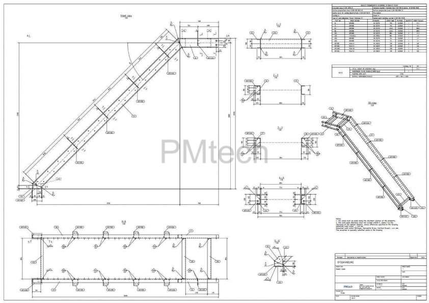
Shop drawings, meticulously developed by experts like PMtech Engineering, serve as essential fabrication and assembly guides for steel structures.
These detailed drawings provide comprehensive specifications on how each steel component should be manufactured, assembled, and installed, ensuring alignment with the design intent. Acting as a critical link between engineering design and physical construction, shop drawings facilitate precise execution on-site.
While workshop drawings (WSD) primarily focus on guiding fabricators through the assembly and erection process, general arrangement (GA) drawings offer essential manufacturing details for individual components. Together, these drawings create a cohesive framework for transforming a conceptual steel structure into a precisely detailed and fully realized construction.
Scan to BIM for an industrial facility
SOFTWARE PRODUCTS: AUTODESK REVIT, LEICA CYCLONE REGISTER 360, AUTODESK RECAP, AUTODESK NAVISWORKS, MAGICAD
PROJECT INFORMATION
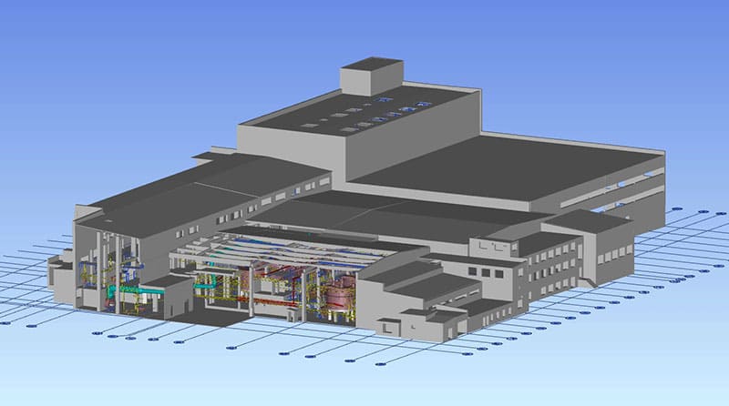
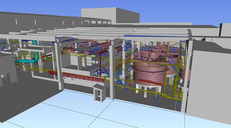
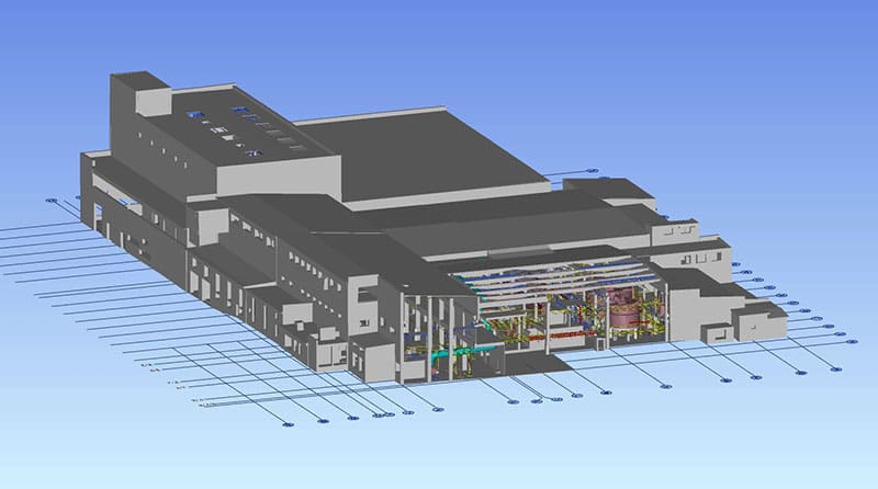
As a company specializing in BIM services, we are highly skilled in handling various tasks, including scanning to BIM for digital twins, architecture-structural, MEPS/HVAC coordination, producing shop drawings, and aligning the model to laser scans or producing as-builts.
PROJECT DESCRIPTION
Digital twinning and laser scanning of refurbishment and extension projects. In this case, our areas of expertise include:
– alignment to point clouds and producing as-builts,
– scan to BIM, 2D to 3D modelling,
– process automation (big data, AI),
– BIM coordination for HVAC, MEP.
The models of the industrial facilities have successfully fulfilled the client’s requirements for Level of Development 400 (LOD400), Level of Information 500 (LOI 500), encompassing both geometric and operation information as specified by the shared parameters.
This has allowed us to align our outputs with their needs while strictly adhering to the BIM Execution Plan (BEP) and Employer’s Information Requirements (EIR). This approach has facilitated a seamless transition from construction to operation, aided by the thorough delivery of COBie datasets that conform to BS 1192-4 standards.
Steel structural design
SOFTWARE PRODUCTS: TEKLA STRUCTURES, DLUBAL RFEM, IDEA STATICA
PROJECT INFORMATION
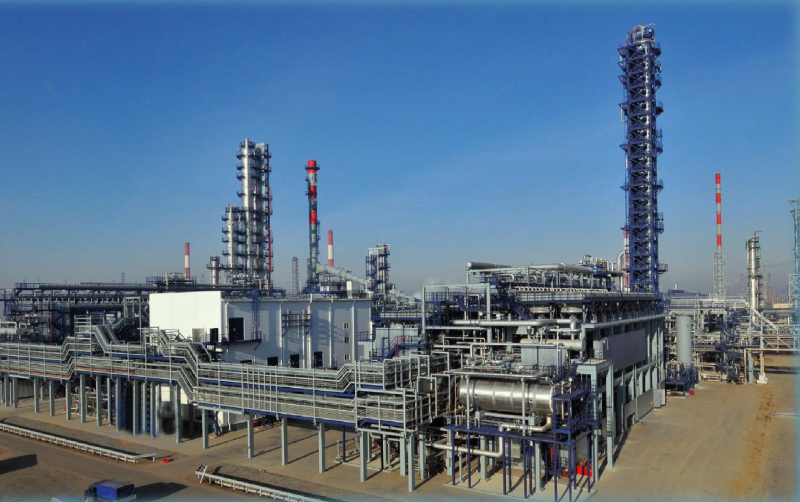
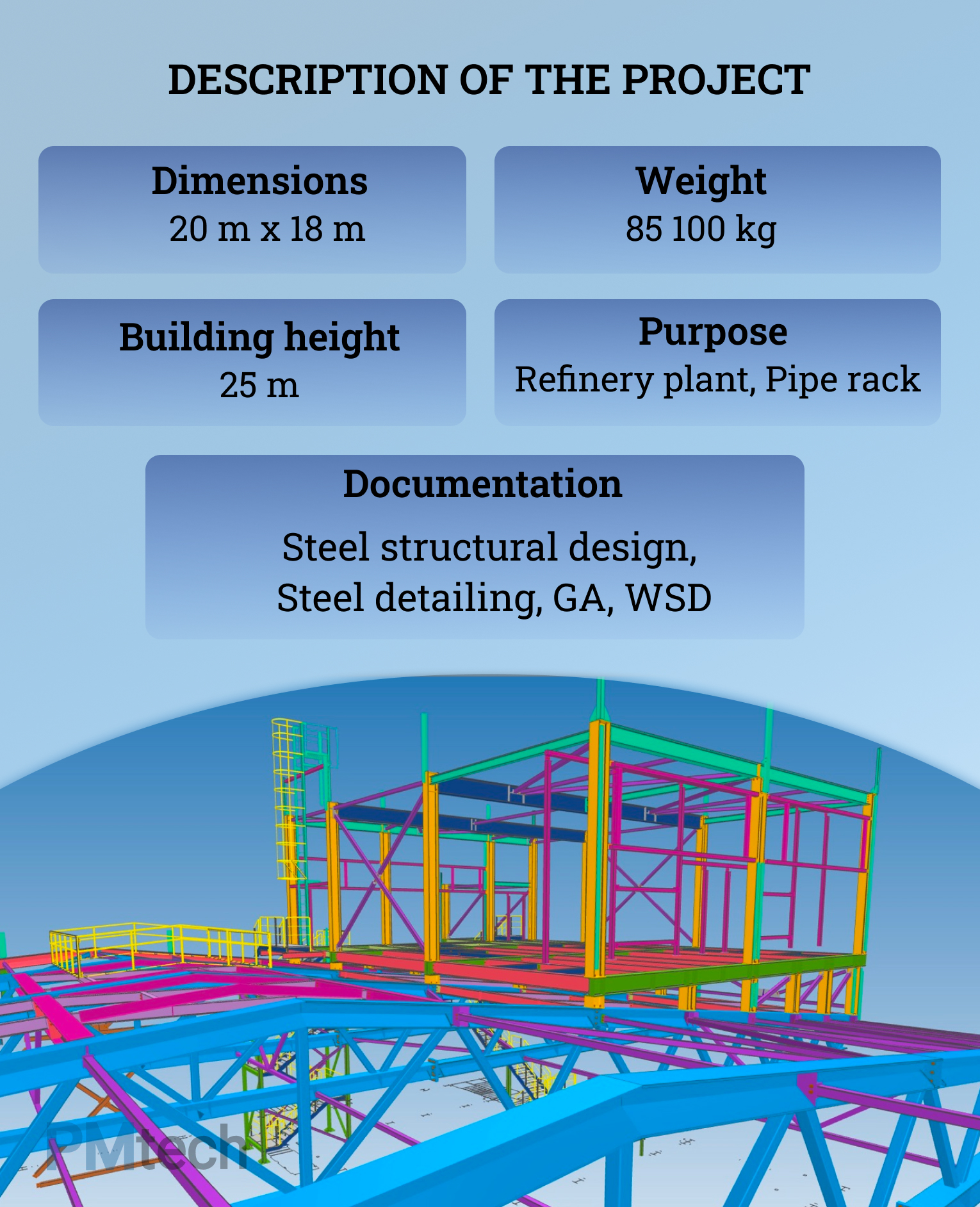
Industrial facility. Refinery Plant
PROJECT DESCRIPTION
PMtech Engineering offers comprehensive solutions to the steel detailing needs of a wide clientele ranging from fabricators, contractors, architects, and engineers. Steel detailing services are of impeccable quality and strictly adhere to international industry standards.
Specialists performed the entire range of work on the design of steel structures:
- calculation of statics in Dlubal RFEM,
- calculation of connections (joints) in IDEA Statica,
- steel detailing and 3d modeling in Tekla Structures,
- advanced bill of materials, single part drawings, erection drawings, assembly drawings
Description of the project:
Purpose: Refinery plant, Pipe rack
Dimensions: 20 m x 18 m
Building height: 25 m
Weight: 85.1 t
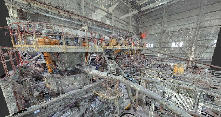
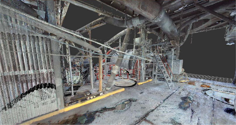
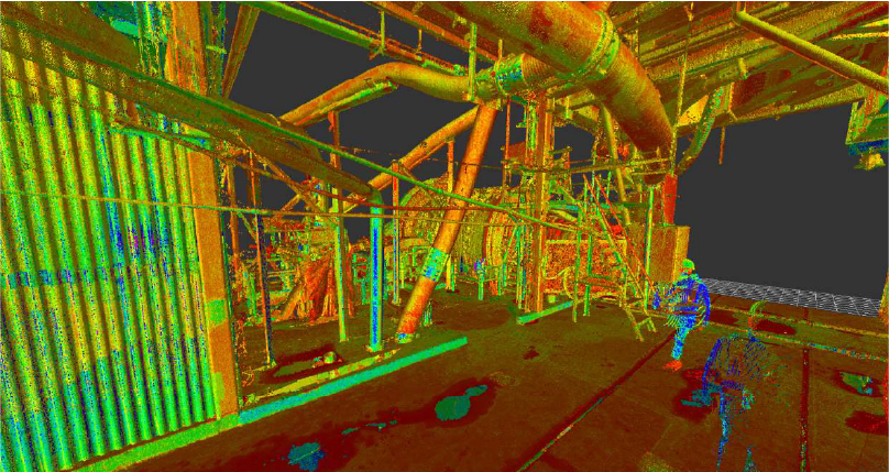
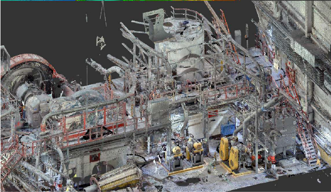
BIM 3D model development based on a Point Cloud data (Digital Twin)
Renovation. Detailed design stage.
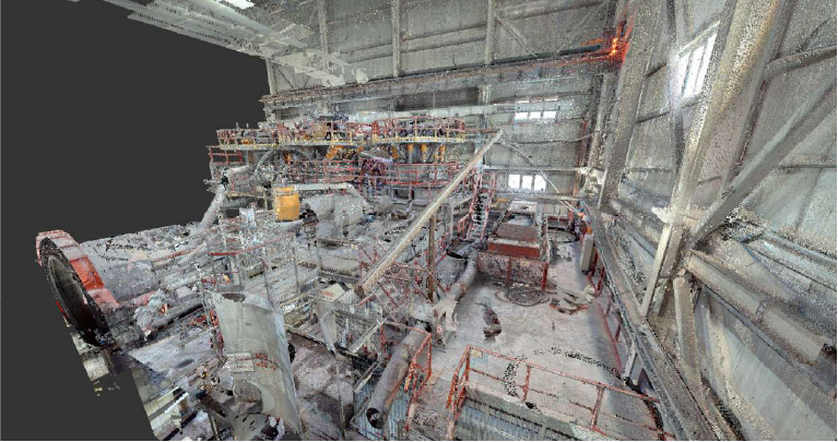
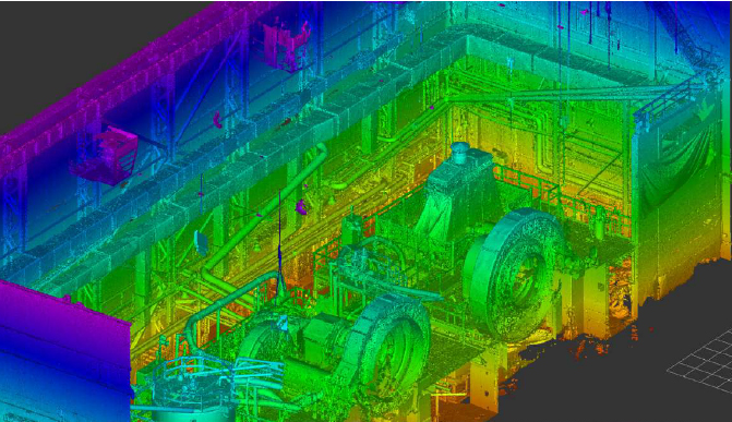
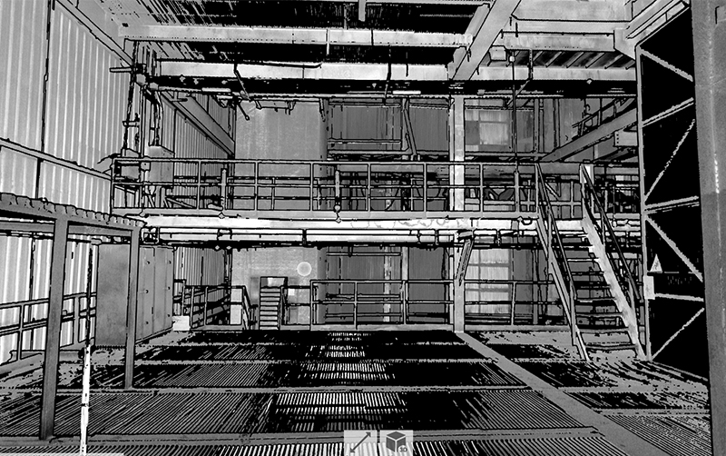
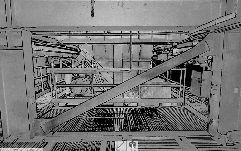
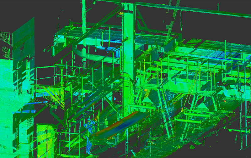
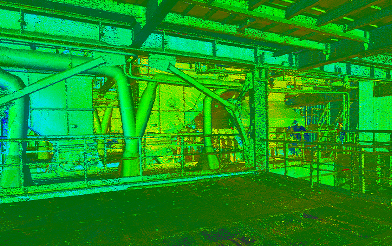
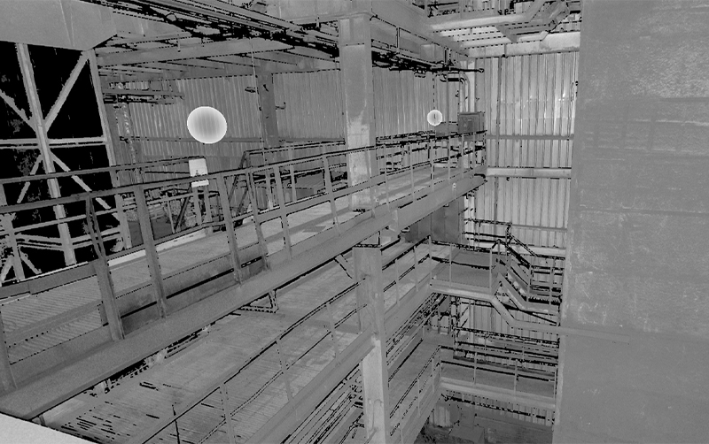
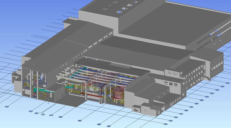
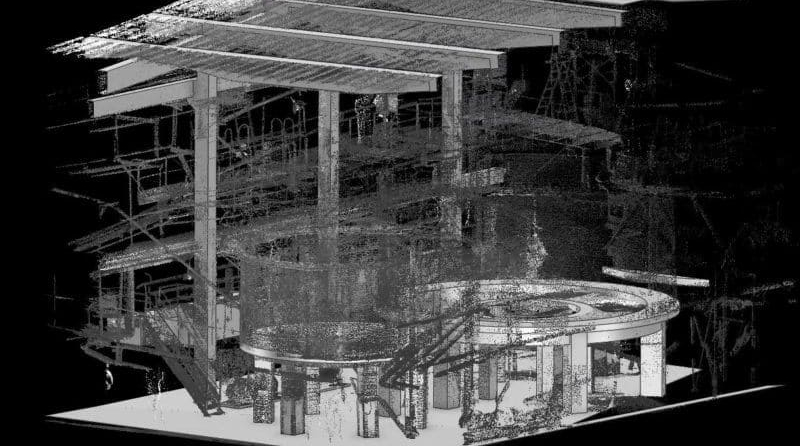
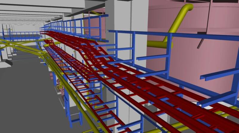
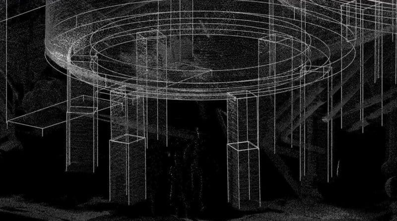
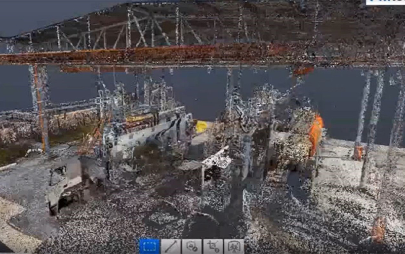
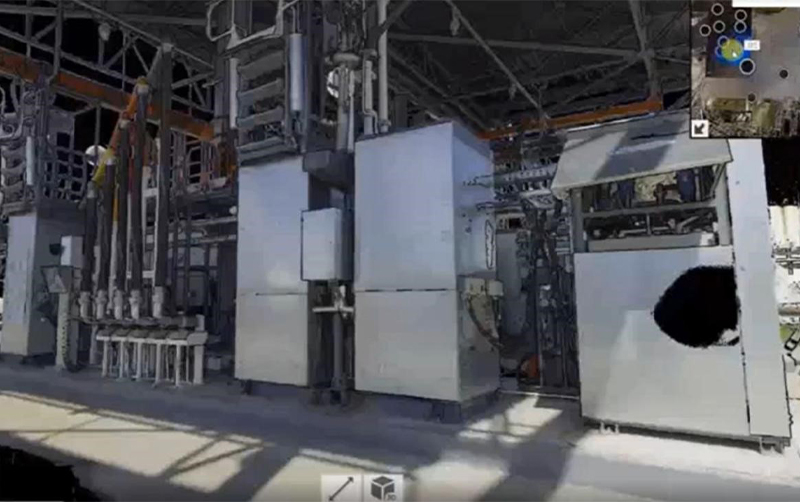
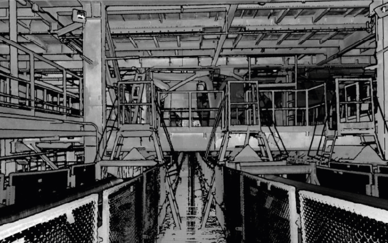
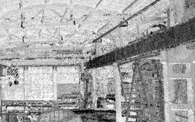
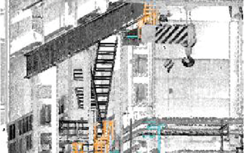
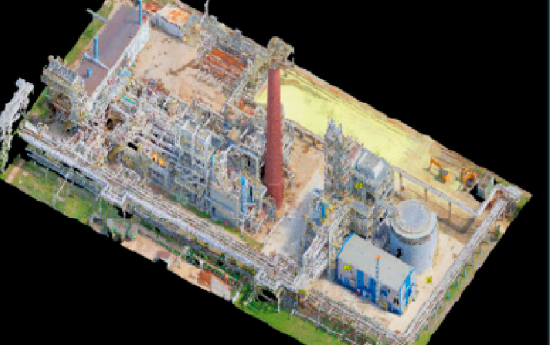
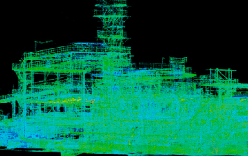
3D-model “As-built” (Scan to BIM) based on cloud point data obtained by laser scanning (Leica Geosystem).
PROJECT DESCRIPTION
Manage point cloud data exchange, manage information quality necessary for BIM execution projects, and assure the 3d model quality by performing consistent BIM model quality checks. The finished model displays the real state of the object at the time of the survey and displays the results of the conducted engineering and geodetic surveys. A detailed executive model will be used for further operations and renovations of the industrial facility.
BIM 3D model of the Mining & Metals complex
Detailed design stage
The objective of this project was to develop BIM and BEP strategy for successful BIM Project execution for operation and maintenance phases.
A 3D model was developed based on 2D drawings, incorporating precise attributes for all 3D elements. A comprehensive clash detection and specification analysis was conducted, generating detailed reports to optimize material selection, assess material properties, and evaluate the characteristics of reinforced concrete and steel structures.
The development of an “As-Designed” BIM model serves as an efficient solution for transitioning from paper-based or outdated data formats. During the conversion to a 3D model, critical design inconsistencies and clashes are identified and resolved. A technically accurate BIM dataset enables precise budget allocation for construction, redesign, and facility management, ensuring cost-effective and well-coordinated project execution.
BIM 3D model of a Chemical Plant based on a Point Cloud data
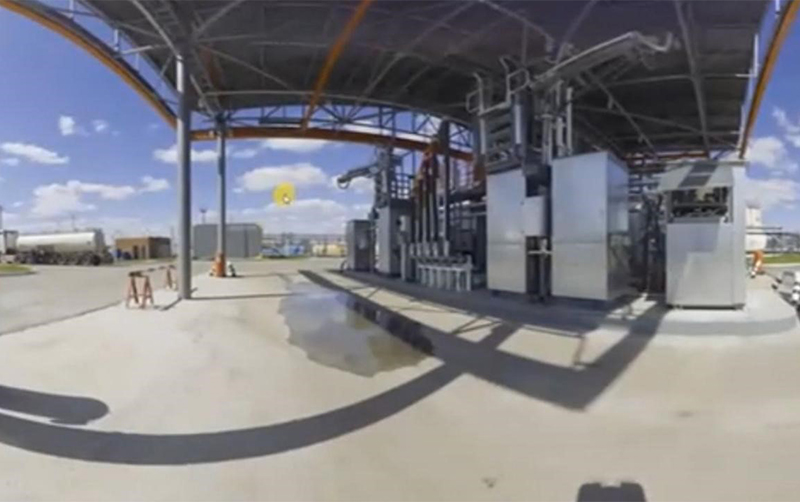
Developing a 3D model “As-built” based on a point cloud obtained by laser scanning data (Leica P40)
PROJECT DESCRIPTION
3D “As-built” model was created according to laser scanning data with filling in technical and technological characteristics (attributes) up to BIM level 6D. All the main parameters were related to the classifier that was passed by the customer. File processing: automatic registration of scans, cleaning and receiving the final .rcp file.
The main task for this project was the creation of a parametric 3D model for further design of additional installations, reconstruction of the workshop’s internal systems and equipment modernization. A special feature of the work is the fact that the acquisition of a point cloud through scanning was carried out without interrupting the production process.
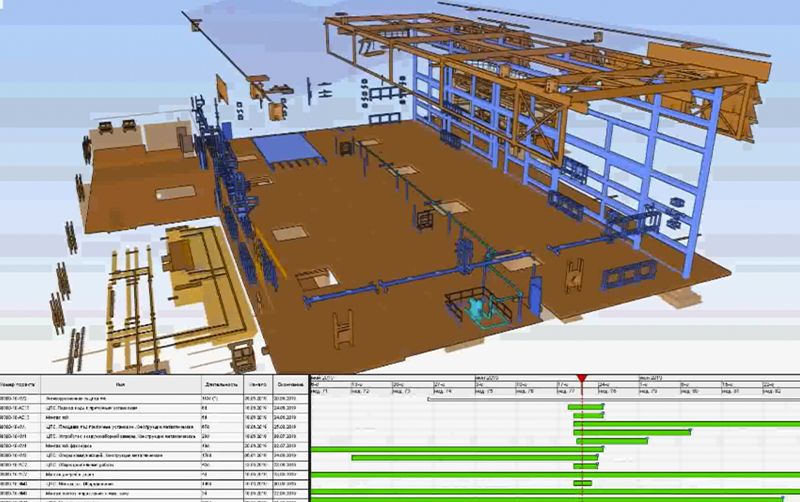
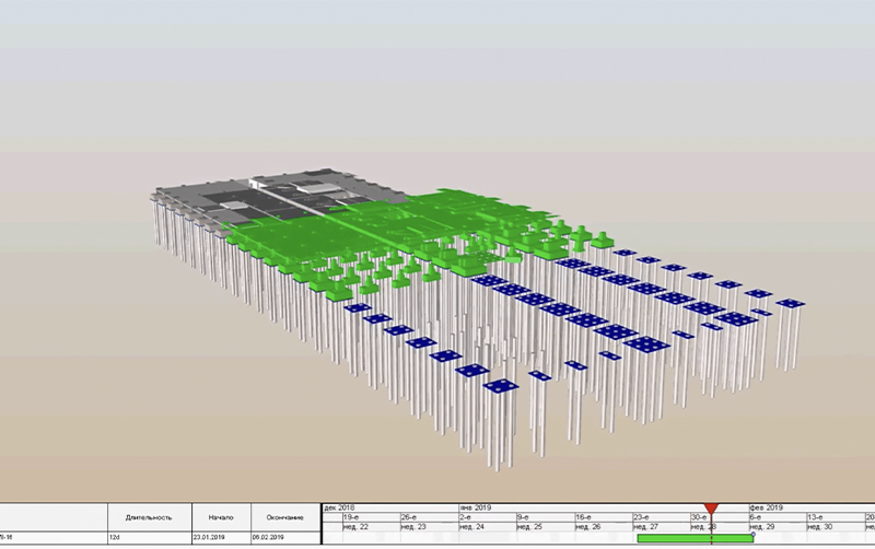
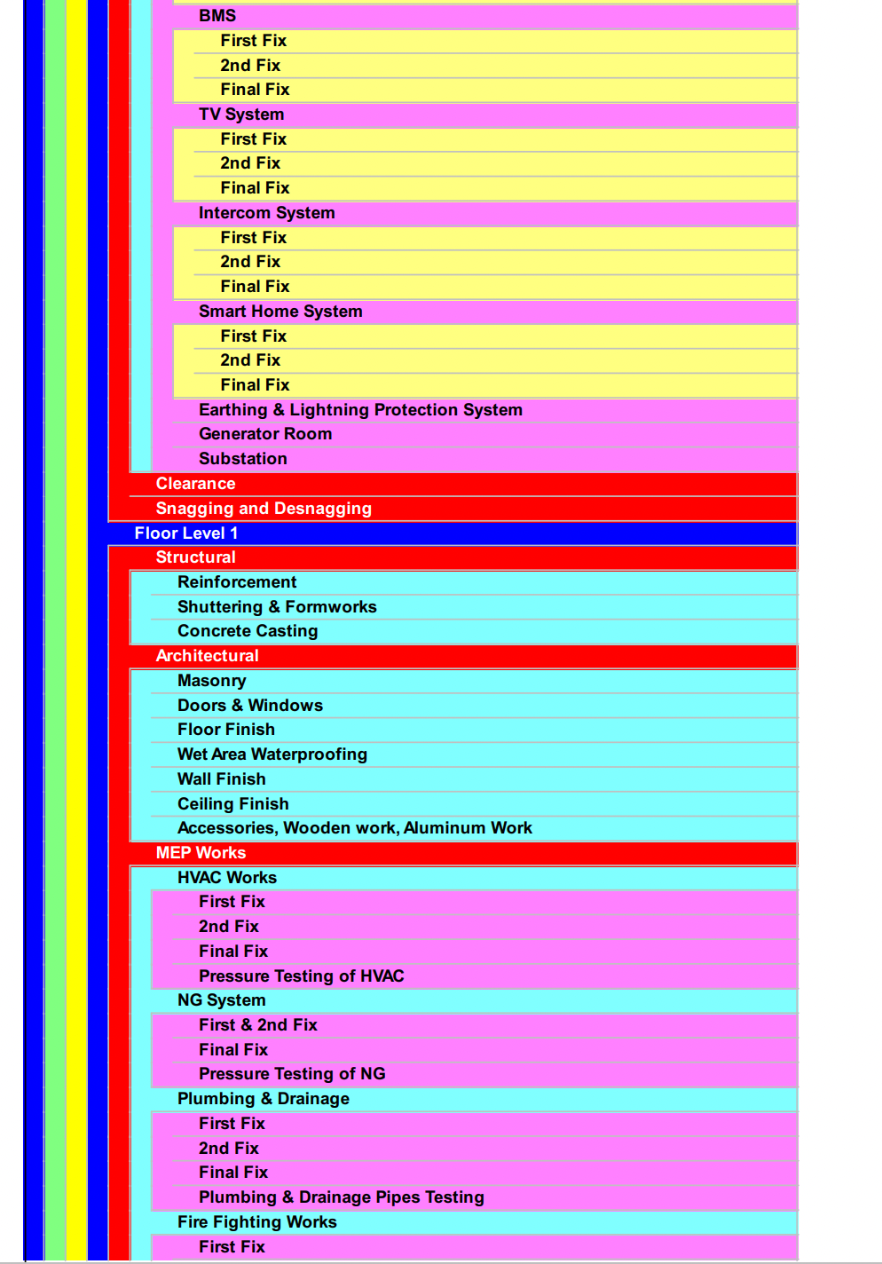
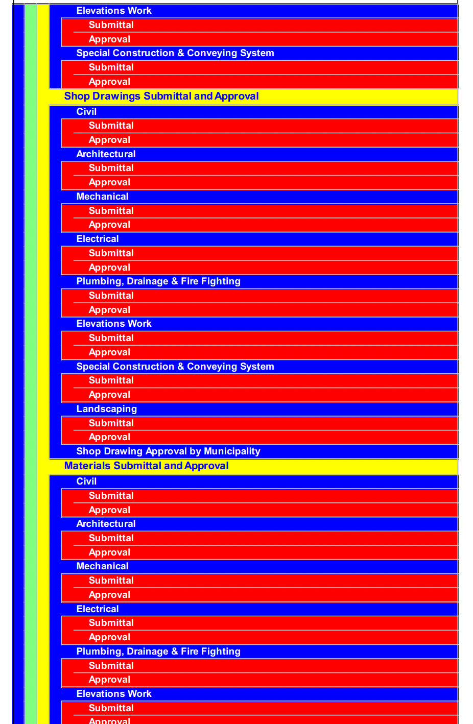
BIM 4D Calendar time scheduling and project planning
Construction (support stage). Detail design stage
Visual simulation (4D BIM) of the sequencing of the construction phase and the construction schedule design using the 3D model.
Our 4d BIM experience on YouTube channel:Click
The digital twin of the Oil Base
● for existing buildings for its further advanced and smart maintenance
● when restoration, modernization is performed.
enables to safely capture measurements in traditionally difficult-to-navigate environments such as working plants without disrupting the facility’s day-to-day operations.
● Gathering and digitization of all the operational and executive documentation including construction design supervision reports, and archive forming.
● Creating the 3D model by filling in the information and linking the documentation to the elements.
From the environment to the structure and everything inside it your buildings can have their 3D BIM model. The digital twin stores data and provide detailed knowledge of the created structure for future maintenance and improvements.
Metallurgical Complex. Reconstruction.
PROJECT INFORMATION
PROJECT DESCRIPTION
- For further reconstruction of the existing workshop and a new equipment installation.
- To make a design of the renewed project in BIM where the new equipment must be fitted into the facility correctly
in relation to its dimensions and the existing size of the workshop.
Oil Refinery Plant (Modernization)
PROJECT INFORMATION
Surveying, laser scanning,
Formation of initial data for the primary oil refining unit (UPN) for modernization.

